Wednesday 20 June 2012

RPM signal issues


Time for a bit of an update on this. Unfortunately, I am still chasing a clean, reliable rpm input to the ECU. I have given up on trying to take the input from the coil packs, simply because I would like to have the Microsquirt control ignition timing as well as fuel at some point so there is no point going through the pain twice.

I have made some bit of progress though. First is the trigger wheel definition. I made the fundamental mistake of not physically looking at the wheel myself and relying on pictures from the manual. Of course I didn’t realise that I was looking at pictures of a trigger wheel on an mc17 CBR250 which has the 8-1 trigger wheel. It was only after one of the members on the cbr250.com forum questioned me on this that I realised that the mc22 
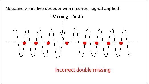
trigger wheel was a 12-3 definition. That explained some of the erratic signals and why the rpm was jumping to over 21,000rpm at idle. The ECU was expecting teeth where there was none and gaps where there were teeth.

The problem is that this didn’t fix the issue… It did make it better as in the signal peaks read by the ECU were consistent with the actual running rpm of the engine but the signal was still constantly dropping to zero. I tried a few combinations of noise filters within the Microsquirt software but to no avail. After contacting DIYAutotune who I bought the Microsquirt from, they have advised that I try switching to MSII/Extra firmware as it includes some extra diagnostics tools to help isolate the issue. One of these is the trigger tooth logger. I should be able to use this function to see if the ECU is actually reading each trigger tooth correctly and thereby tell me whether I need to concentrate on the VR signal coming into the ECU, or the settings within the ECU.

I have an idea that if the signal entering the ECU is the issue then I will attempt to convert the VR signal to a Hall signal externally using an LM1815 chip and feed that into the ECU. The ECU should be able to read the square wave Hall signal much more easily and cleanly than the AC VR signal.

Also, I have decided to go ahead and modify the GSR400 throttle bodies right away rather than attempt to tune the system on modified carburettors and then do it all again with throttle bodies. I am currently preparing the drawings for the throttle bodies, butterfly valve rods, fuel rail and fuel rail mount adapters so that I can get quotes from a few machine shops and get it kicked off. Once the throttle bodies are ready, that will be a major part of the project complete.

Tuesday 8 May 2012

Sensor callibration

You've got to love long weekends! I made a bit of progress on the bike the last few days although not quite as much as I would have hoped.

First off was getting my spark back... a little embarassing but it turned out to be stupidly simple! For some reason I still havent figured out, I had decided it was a good idea to disconnect the coils from the loom when I started stripping the bike. And since the connector for the coils is in behind the frame, I didn't actually cop it until after I had tested the VR sensor, CDI, fuses and various other things!

One step in the right direction was to calibrate my MAP sensor. The ECU had been using the calibration data for a common GM sensor to convert the output voltage of my Denso sensor to pressure readings and it had been a bit off. (reading ~190kPa at atmospheric pressure).

I was able to borrow a vacuum gauge from a friend of a friend and connect it via a T-connector into the vacuum tube so the MAP sensor was on one branch of the connector and the gauge was on the other. What I did then was to run the engine, pinch the vacuum tube with a pliers before the T-connector to trap the vacuum and read off voltage from the MAP sensor and vacuum in inches-Hg from the gauge. I was able to get several readings for different pressures by revving the engine to different speeds and closing the throttle to take advantage of the collapsed vacuum formed after the butterfly valves. This allowed me to get as many varied results as possible.


I input the data into a spreadsheet and converted the inches-Hg readings to kPa absolute. I then graphed the data and drew a straight line of best fit and extended the range to go from 0V to 5V as these are the values needed to calibrate the sensor in TunerStudio.


I thought reading the values of pressure read directly from the graph were too inaccurate so I ended up calculating the slope of the line and coming up with an equation for the line and calculating the values of pressure at V=0V and V=5V. I inputted the values into TunerStudio and burned them to the ECU and, voila! Correct pressure readings.


Just to show the pressures being experienced in the manifold at engine idle speed here is another screenshot:


I also hooked up the intake air temperature (IAT) sensor and verified that was working ok.

I was hoping to get the RPM input sorted over the weekend aswel as this would pave the way to get some real work started on installing the rest of the fuel injection hardware. However it proved a little too elusive for me. I tried two different ways of getting a signal to the ECU. The first was to share the VR signal input from the pulse generator with the stock CDI.

The mc22's ignition unit takes its rpm and crank position inputs from an 8-1 trigger wheel mounted on the end of the crank. The wheel induces an alternating voltage across a variable reluctor (VR) sensor as the teeth pass by the sensor. As the wheel has one tooth missing it produces an AC voltage with 7 peaks (7 teeth) and a gap of once per revolution as the space where the missing tooth is passes the sensor. The ignition unit uses the resultant voltage signal to read engine rpm and determine engine position. Since a picture speaks a thousand words, this is pretty much what the output from the VR sensor should look like:


In theory, I should be able to simply define the trigger wheel being used and the ECU should be able to read the engine RPM straight away. Unfortunately this wasnt the case... I was able to get some signal from from the sensor but it looks like the signal was too noisy to be used properly with the microsquirt. It was erratic and would jump from reading 0rpm, to over 21,000rpm even as the engine was only idling. I logged the data over a period of a few seconds in order to get a better picture of what was happening and it is pretty clear how often the signal jumps. The graph you need to be looking at is the top bar and the RPM signal is the yellow line.


I also tried to get an RPM signal from the coil inputs but no success at all. Given that I would eventually like to get the microsquirt controlling ignition as well as fuel I would like to get the VR sensor input working properly. I suspect this will involve some circuitry placed between the sensor and the ECU in order to clean up the signal enough for the microsquirt to be able to use it. This will need some more research though. The sooner I can get a clean and reliable RPM signal to the ECU, the sooner I can get the injectors installed and hooked up.

Monday 30 April 2012

Connected

After a bit of research into the communication problem between the laptop and the ECU, it became clear that the issue was with the serial to USB adapter. Seemingly its not at all uncommon for an ECU to refuse to communicate through an adapter and which adapters work and which don't tends to be a hit-and-miss thing.

So rather than buying another adapter and hoping it would work, I decided to skip the problem altogether and try to pick up an old laptop with a direct serial port. It didnt take me long to find an old Dell Latitude C610 on ebay and got it posted for about €50 all in. Not a bad deal.
This is now my dedicated tuning laptop. It will never get connected to the internet if I can help it and it will only ever run software needed for tuning.


As soon as I was able to verify communication with the ECU, I took the opportunity to upload the latest firmware version to the microsquirt before I did anything else. It was nice to see it complete rather than run into errors as it had two weeks before!


I then set up the project in the tuning program, TunerStudio. Once the basics were set up I needed to fix the .ini file which keeps all the base settings so that the ECU would be able to run my engine properly. The standard settings will only allow a max rev limit of 15,000 RPM so to allow for the 19,000 rev limit on the mc22, that needed to be changed. Luckily the .ini file can be easily edited in a basic text editor.

The only two sensors I had connected to be able to read was my RPM signal and the MAP sensor. The MAP sensor is giving a reading fine and when the engine is cranked over, the pressure drops as expected when the throttle is closed. It does need to be calibrated properly though as it is currently reading 190kPa at normal atmospheric pressure. This should be around 100kPa. I will need to try and find calibration data for that particular MAP sensor.

I then tried to start the bike on carburettors to see if I was getting an RPM signal. Thats when another problem reared its head... The bike wouldnt start... I thought it might be that the signal from the pulse generator didnt like being shared with the microsquirt but when I disconnected that, it still refused to start. I thought it funny that there were no pops which indicated it was even trying to start so I pulled out a plug to verify if I had spark. No spark.

At the moment I can only guess that tapping into the wires from the pulse generator is causing some sort of short circuit or other problems but I had no time to investigate further this weekend. It will have to wait until next time I get to it and I can do some more tests.

TunerStudio interface showing MAP reading. All other readings are default as there is no sensors connected

Thursday 12 April 2012

Work begins!

After many months researching and planning the project, I eventually got it kicked off properly. I had a long weekend just gone and was able to tear into it. The bike is now officially off the road and it wont be going back onto it until its running on injectors.

First thing was to get the MAP sensor hooked up. Since I wont have a TPS on the carbs for the initial testing, I will need to use the speed/density algorithm on the Microsquirt and that means using a MAP sensor to determine engine loading. Lowest manifold pressure will be at idle with pressure increasing up until full throttle. As the engine won't be running forced induction, the pressure will stay below atmospheric so a simple MAP sensor is enough. Lucky for me, there was a sensor attached to the GSXR750 throttle bodies so I was able to use that.

I bought one more brass vacuum nipple to replace the blanking screw thats usually on the cylinder #4 vacuum port.


Individual throttle bodies can have problems when it comes to reading MAP as there is no plenum between the throttle plates and inlet valves to even out the pressure variations. The space between the throttle plate and inlet valve is typically not much bigger than the cylinder volume, if at all. This causes big fluctuations in pressure especially at idle. What I have seen previously is the use of a small fuel filter in the vacuum line before the MAP sensor to act as a small plenum and clean up the MAP signal coming from the sensor. The GSXR throttle bodies just had four individual vacuum lines coming together and connecting to the MAP sensor so I decided to try that first and if the signal turned out too noisy for the ECU to handle, I could work at cleaning it up then.


I took the sensor and hosing off the GSXR throttle bodies and fitted it to the four vacuum nipples.


Next step was install the Microsquirt unit. I decided to mount it on the back "wall" in the "boot" space underneath the pillion seat and have the harness run through the bottom left corner, out along beside the CDI and along the frame. Any fuses and relays could be put in the "boot" aswel to allow them to be changed easily. The Microsquirt itself is mounted with four bolts. I will be adding rubber washers between the bolts and mounting surface to dampen vibrations.


The amount of wires hanging out of the harness is pretty daunting so I figured I would seperate it out into manageable sections and work my way through it that way. It may not be the perfect plan but I figured something like the following should be manageable:
  1. Ground connections
  2. Power connections including relays and fuses
  3. Sensors
  4. Fuel pump
  5. Injectors

The ground connections seemed like the logical place to start as I wanted to ensure that all grounds were connected back to the same point to avoid ground loops or other issues with sensors. There is a great wiring diagram provided on the Microsquirt website that helped with the wiring (shown below). That along with a description of all pin connections got me through it. The nice thing is that all sensors, coils and injectors are grounded though the ECU so all I had to do was gound the ECU and provide a place to plug in a lambda sensor controller as that would only be used for testing.
MS3 wiring diagram courtesy of http://www.useasydocs.com/quickstart.htm. (copyright Bowling & Grippo & Gardiner)


After that came power. This is where things started to look messy. I needed to supply power to two relays, the main relay for switching on the ECU with the ignition and the fuel pump relay that would be controlled by the ECU itself. All the power connections had to run through fuses aswel so there are a few wires that look pretty messy outside the harness. Since I still haven't sourced a fuel pump I only connected the main relay for now to get power to the ECU.


I took the opportunity to wire up whatever sensors I had at this point aswel. I tapped into the wires from VR sensor from the crank rotor for an RPM signal. I could have used the signal from the negative wires on the coils but I plan on eventually having the Microsquirt control ignition as well as fuel so I figured just to go straight for the crank position sensor. I hope the signal from the VR sensor can be shared now...

Unfortunately I ran into a brick wall though when I went to connect the Microsquirt to my laptop and test the polarity of the VR sensor connections. I couldnt get the ECU to talk to the laptop. The tuning program, TunerStudio, was just not recognising the Microsquirt and uploading new firmware failed aswel. I verified the 12V supply to the ECU as well as continuity on the two ground pins so thats not the issue. I did a loopback test on my serial cable to check that the com port was sending and receiving information properly and that checks out too.

After trying everything on the Microsquirt troubleshooting guide with no success, I emailed the guys in DIYAutotune where I bought the Microsquirt to see if they could help with the troubleshooting. Hopefully they will be able to shed some light on the subject.

For now though I can work on getting the injectors installed and the fuel pump and plumbing hooked up. While the bike sits there stripped down and a mess of wires.


I will keep this updated as I progress.

Background

I have eventually started this project so its as good a time as any to start this blog. Before getting into the details, I suppose its better to give a bit of background on the project.

The bike in question is a 1996 Honda CBR250RR mc22. I have had the bike for over 3 years and pretty much learned to ride on it. Too much money and time has been spent on it to justify selling it so instead I'm using that as justification to spend even more money on it!


The idea of an EFI conversion started a few years ago through conversations with friends but was always put off as I didnt have the money or the mechanical knowledge. Now though I've come a long way with the mechanics and I have the money also. The single biggest driver for the project though was the challenge. For anyone who isn't familiar with these bikes, the engine is a 250cc inline-four, 4-stroke which puts out 40-45bhp in standard tune depending on the model. It manages this output by revving to a 19,000RPM redline. As standard, fuelling is provided through four 29mm carburettors. While the standard carburettors are more than adequate to provide fuel, the attraction of EFI on the bike is to have total control over the bikes fuelling curve just by plugging in a laptop and also to potentially have a much quicker throttle response due to not having to wait for the vacuum slides to react to flow changes through the venturi.

The price of these benefits though are the complications involved in the conversion.
  • Cost. ECUs are not cheap. Since no model of this bike was ever fuel injected, I have to borrow components from other bikes and fit them together to make up a working system. Since I want total control over the fuelling, I couldnt just use an ECU off a newer bike either. The ECU needed to be an aftermarket, programmable unit. I decided to use the Microsquirt ECU by Bowling & Grippo. The reason being it is an opensource ECU so all firmware upgrades and tuning software are free and there is plenty of support available through forums.
  • Injector sizing. The injectors need to have a high enough flow rate to supply the required amount of fuel needed at high RPM within the limited time available. At 19,000RPM, there is only 0.0063 seconds available to inject the fuel. This is the time taken for the engine to cover 720 degrees of rotation so it assumes the injectors are constantly open (100% duty cycle). It is recommended that injectors should not be run at more than 80% duty cycle so that actually leaves only 0.00505 seconds to inject the fuel for each engine cycle. The saving grace with the engine though is its small cylinder size. With a capacity of only 63cc per cylinder, the required fuel is not too high. Taking the above into account and making some assumptions regarding AF ratio and volumetric efficiency, I calculated the injectors should flow 160-170 cc/min. If the injectors are too big, there can be issues tuning at idle and low RPM as the injectors could possibly provide too much fuel during only the opening and closing stages. 
  • Space constraints. The mc22 is a small bike and the majority of space underneath the tank is already taken up with other systems. Fitting all the components for an EFI conversion would be a challenge.
  • Throttle bodies. Most existing banks of throttle bodies are designed for much bigger engines from 600cc upwards. The problems with these are the bore size is too big so adapters would need to be made to fit the throttle bodies to the cylinder inlet stubs. The other problem with too large throttle bodies is that the engine would reach a state of effective 100% throttle very early and so slow speed and off-idle response would be very snatchy and make the bike almost impossible to ride at anything other than full throttle. Another problem is the width of the bigger throttle bodies just would not fit between the frame rails of the CBR250. The throttle bodies need to be under 300mm wide to fit the CBR.
  • Electrical power. The CBR250 does not have much leftover power being generated at idle which is a potential problem when running a high pressure fuel pump required for fuel injection. Fuel pumps typically draw 3-5 Amps. This current draw would put a strain on the battery and charging system if the bike were to be left running at idle for any length of time. To help solve the problem, I installed LED tail lights in place of bulbs and also LED dash lights to save that bit more power for the pump.
 The throttle body issue seemed to be the biggest issue to overcome so I made it the first. After a lot of research, I eventually came to the conclusion that I would use a set of throttle bodies from a Suzuki GSR400. These were chosen because they had the same diameter intake stubs as the stock carburettors and so could be fitted directly to the standard intake rubbers given the correct spacing. I bought the throttle bodies from a motorcycle breakers in Japan and had them shipped over. They look like they will do the job perfectly although they will need some modification to get the spacing right for the CBR250. The two castings will need to be machined and new throttle plate rods will need to be made to suit the new spacing.


Given the amount of work and the expense in modifying the throttle bodies, I decided to first test the EFI by mounting a bank of injectors inside the stock airbox and spraying the fuel down into the carburettor velocity stacks. I plan to remove the slide springs and hold them open so that the carburettors act as much like throttle bodies as possible. Once I can verify that the EFI works I will go ahead and modify the GSR400 throttle bodies and make the setup more permanent.

I was lucky enough to find a secondary injector rail from a 2003 CBR600RR for pretty cheap on ebay in the US. This was good for a few things. First is the design of the secondary injector rail is such that it will be easy to install it in the airbox with as little modification as possible. Second is the flow rate of the injectors on the rail are only about 180 cc/min and so are almost perfect to use on the project. An added bonus is that the injectors fit perfectly into the GSR400 throttle bodies.


I also happened across a free set of throttle bodies from a 2001 GSXR750! While the throttle bodies and injectors are useless for the project, they will be very useful as they came with MAP (Manifold Absolute Pressure) sensor, TPS (Throttle Position Sensor), fuel pressure regulator and fuel rail that should be easily modified to fit the GSR400 throttle bodies.