You've got to love long weekends! I made a bit of progress on the bike the last few days although not quite as much as I would have hoped.
First off was getting my spark back... a little embarassing but it turned out to be stupidly simple! For some reason I still havent figured out, I had decided it was a good idea to disconnect the coils from the loom when I started stripping the bike. And since the connector for the coils is in behind the frame, I didn't actually cop it until after I had tested the VR sensor, CDI, fuses and various other things!
One step in the right direction was to calibrate my MAP sensor. The ECU had been using the calibration data for a common GM sensor to convert the output voltage of my Denso sensor to pressure readings and it had been a bit off. (reading ~190kPa at atmospheric pressure).
I was able to borrow a vacuum gauge from a friend of a friend and connect it via a T-connector into the vacuum tube so the MAP sensor was on one branch of the connector and the gauge was on the other. What I did then was to run the engine, pinch the vacuum tube with a pliers before the T-connector to trap the vacuum and read off voltage from the MAP sensor and vacuum in inches-Hg from the gauge. I was able to get several readings for different pressures by revving the engine to different speeds and closing the throttle to take advantage of the collapsed vacuum formed after the butterfly valves. This allowed me to get as many varied results as possible.

I input the data into a spreadsheet and converted the inches-Hg readings to kPa absolute. I then graphed the data and drew a straight line of best fit and extended the range to go from 0V to 5V as these are the values needed to calibrate the sensor in TunerStudio.

I thought reading the values of pressure read directly from the graph were too inaccurate so I ended up calculating the slope of the line and coming up with an equation for the line and calculating the values of pressure at V=0V and V=5V. I inputted the values into TunerStudio and burned them to the ECU and, voila! Correct pressure readings.

Just to show the pressures being experienced in the manifold at engine idle speed here is another screenshot:

I also hooked up the intake air temperature (IAT) sensor and verified that was working ok.
I was hoping to get the RPM input sorted over the weekend aswel as this would pave the way to get some real work started on installing the rest of the fuel injection hardware. However it proved a little too elusive for me. I tried two different ways of getting a signal to the ECU. The first was to share the VR signal input from the pulse generator with the stock CDI.
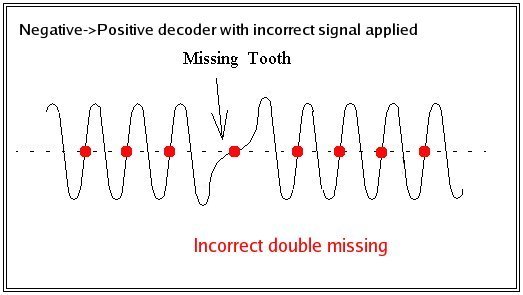
The mc22's ignition unit takes its rpm and crank position inputs from an 8-1 trigger wheel mounted on the end of the crank. The wheel induces an alternating voltage across a variable reluctor (VR) sensor as the teeth pass by the sensor. As the wheel has one tooth missing it produces an AC voltage with 7 peaks (7 teeth) and a gap of once per revolution as the space where the missing tooth is passes the sensor. The ignition unit uses the resultant voltage signal to read engine rpm and determine engine position. Since a picture speaks a thousand words, this is pretty much what the output from the VR sensor should look like:
In theory, I should be able to simply define the trigger wheel being used and the ECU should be able to read the engine RPM straight away. Unfortunately this wasnt the case... I was able to get some signal from from the sensor but it looks like the signal was too noisy to be used properly with the microsquirt. It was erratic and would jump from reading 0rpm, to over 21,000rpm even as the engine was only idling. I logged the data over a period of a few seconds in order to get a better picture of what was happening and it is pretty clear how often the signal jumps. The graph you need to be looking at is the top bar and the RPM signal is the yellow line.

I also tried to get an RPM signal from the coil inputs but no success at all. Given that I would eventually like to get the microsquirt controlling ignition as well as fuel I would like to get the VR sensor input working properly. I suspect this will involve some circuitry placed between the sensor and the ECU in order to clean up the signal enough for the microsquirt to be able to use it. This will need some more research though. The sooner I can get a clean and reliable RPM signal to the ECU, the sooner I can get the injectors installed and hooked up.
First off was getting my spark back... a little embarassing but it turned out to be stupidly simple! For some reason I still havent figured out, I had decided it was a good idea to disconnect the coils from the loom when I started stripping the bike. And since the connector for the coils is in behind the frame, I didn't actually cop it until after I had tested the VR sensor, CDI, fuses and various other things!
One step in the right direction was to calibrate my MAP sensor. The ECU had been using the calibration data for a common GM sensor to convert the output voltage of my Denso sensor to pressure readings and it had been a bit off. (reading ~190kPa at atmospheric pressure).
I was able to borrow a vacuum gauge from a friend of a friend and connect it via a T-connector into the vacuum tube so the MAP sensor was on one branch of the connector and the gauge was on the other. What I did then was to run the engine, pinch the vacuum tube with a pliers before the T-connector to trap the vacuum and read off voltage from the MAP sensor and vacuum in inches-Hg from the gauge. I was able to get several readings for different pressures by revving the engine to different speeds and closing the throttle to take advantage of the collapsed vacuum formed after the butterfly valves. This allowed me to get as many varied results as possible.

I input the data into a spreadsheet and converted the inches-Hg readings to kPa absolute. I then graphed the data and drew a straight line of best fit and extended the range to go from 0V to 5V as these are the values needed to calibrate the sensor in TunerStudio.

I thought reading the values of pressure read directly from the graph were too inaccurate so I ended up calculating the slope of the line and coming up with an equation for the line and calculating the values of pressure at V=0V and V=5V. I inputted the values into TunerStudio and burned them to the ECU and, voila! Correct pressure readings.

Just to show the pressures being experienced in the manifold at engine idle speed here is another screenshot:

I also hooked up the intake air temperature (IAT) sensor and verified that was working ok.
I was hoping to get the RPM input sorted over the weekend aswel as this would pave the way to get some real work started on installing the rest of the fuel injection hardware. However it proved a little too elusive for me. I tried two different ways of getting a signal to the ECU. The first was to share the VR signal input from the pulse generator with the stock CDI.
The mc22's ignition unit takes its rpm and crank position inputs from an 8-1 trigger wheel mounted on the end of the crank. The wheel induces an alternating voltage across a variable reluctor (VR) sensor as the teeth pass by the sensor. As the wheel has one tooth missing it produces an AC voltage with 7 peaks (7 teeth) and a gap of once per revolution as the space where the missing tooth is passes the sensor. The ignition unit uses the resultant voltage signal to read engine rpm and determine engine position. Since a picture speaks a thousand words, this is pretty much what the output from the VR sensor should look like:
In theory, I should be able to simply define the trigger wheel being used and the ECU should be able to read the engine RPM straight away. Unfortunately this wasnt the case... I was able to get some signal from from the sensor but it looks like the signal was too noisy to be used properly with the microsquirt. It was erratic and would jump from reading 0rpm, to over 21,000rpm even as the engine was only idling. I logged the data over a period of a few seconds in order to get a better picture of what was happening and it is pretty clear how often the signal jumps. The graph you need to be looking at is the top bar and the RPM signal is the yellow line.

I also tried to get an RPM signal from the coil inputs but no success at all. Given that I would eventually like to get the microsquirt controlling ignition as well as fuel I would like to get the VR sensor input working properly. I suspect this will involve some circuitry placed between the sensor and the ECU in order to clean up the signal enough for the microsquirt to be able to use it. This will need some more research though. The sooner I can get a clean and reliable RPM signal to the ECU, the sooner I can get the injectors installed and hooked up.