Sunday, 8 September 2013

First ride on ignition control

Delayed a bit getting this up so apologies but things have been slow anyway and haven't been getting a lot of time to work on the bike.

First impressions of riding the bike after sorting out the RPM synch loss errors are all positive! The bike revs cleanly and pulls strong all the way to the limiter. I cannot say for certain if that is all due to the new ignition advance curve as I have been running open carbs for testing purposes. (Couldn't be arsed removing the airbox every time I had to go at anything near the carbs basically)

The ride has confirmed that the ignition control is now working perfectly so its ready to progress with the fuelling side of things. Thats a side that needs the most physical work done in terms of pump installation, throttle body manufacture/modification and full wiring so that may take some time yet. I neglected the fuelling side also as I didn't want to use money and time on it only to find the ignition wasn't feasable.

Data log extract from ride showing rev limiter


Monday, 29 July 2013

Ignition Issues Sorted

I am delighted to say that after a much longer time than I had planned on, I have found all 17,800rpm within the microsquirt!!

As it turns out the internal noise filter settings that were the issue. They were causing more problems than they solved. I started with running the bike with higher than standard noise filter settings but immediately became clear that was the wrong way to go as the engine hit a limiter at only about 5-6k rpm. I then started reducing each noise filter a little at a time which gave slightly better results every time. Eventually turning them all off altogether got me very close to where I needed to be (16,800rpm) but it still wasn't enough. I was still getting synch loss errors at high rpm.

Further research suggested that simply soldering in a 10-20k resistor into each of the wires coming from the VR sensor should fix the problem. I tried a 10k resistor first and straight away the issue disappeared! Now the engine revs cleanly and smoothly all the way to the preset limiter every time with no synch loss errors recorded on the data logs.


Log below and a ride log and video will follow.


Log of static engine run to limiter showing no synch loss errors through the range

Monday, 10 June 2013

Almost there

Before progressing any further with the injection side of things I wanted to make sure that the ignition control was working as expected throughout the range. That meant actually going out and riding the thing with the laptop plugged into the ECU datalogging while riding.

The first time I took the bike out I noticed straight away that it didn't seem to be revving as high or as freely as before. As I had no dash connected, I wasn't able to tell what the issue was until I pulled the datalog. The bike seemed to refuse to rev above 12,500rpm. After riding and logging some more times I was getting a clearer idea of what was happening. The power appeared to flatten out more as the revs grew higher and eventually there was just not enough power to pull anymore after 12,500rpm. At first I thought it was spark timing retard as the revs grew (hardware latency) but a quick test with the timing light debunked that theory. The small amount of retard I was seeing as the revs grew could easily be put down to lag in the timing light itself.

I left the problem simmer with me for about a week and while doing some research on dwell duration on the CBR coils and typical spark durations, I figured I had the root of the problem. The MS documentation suggested a typical max dwell duration of 3ms for most coils, so unable to measure the dwell on my coils I went with that number. Additionally, as I had not investigated the spark duration, I left it at its default value of 0.2ms. I discovered that the actual max dwell on the CBR coils was 6ms instead of 3ms. And I also found that typical "normal" spark durations run between 1ms and 2ms. MS works by trying to fit the max dwell duration int a revolution and if the period of a revolution reduces to below the sum of the max spark and dwell durations, it will reduce each duration proportionally to fit in the period. I plotted what was happening with the original numbers and the spark duration was quickly being squeezed down to numbers which would barely allow a spark to occur.

So I reset the dwell and spark durations and went for another ride. The difference was apparent straight away. The engine pulled as hard as it should to higher revs. Although I did stumble into another issue then. The RPM signal dropped at about 14,800rpm which cut spark. The signal was gone for 4 seconds before it reappeared and ignition kicked back in rather suddenly. This is likely to be just a noise filter setting in the microsquirts software but I have not had a chance to play with it since.

Datalog showing 4s period of RPM dropout and also a momentary signal dropout that happened just before the main one. That small downward spike just felt like a misfire at the time


I have not installed the CBR600RR COP just yet as I need to make sure ignition is working properly before ditching the HT leads that the timing light works off of. 

Saturday, 13 April 2013

Ignition!

A bit late updating this but I am delighted to announce I have ignition!!!

I got my transistors in the post a while back so I built the coil driver module and had a crack at starting the bike. At first I was getting a whole pile of nothing, then a few backfires and then a dead battery. I figured I must have had the wrong cylinders at TDC when I calculated the base advance angle so I went back 180 degrees and tried again the next day. It seemed to be making an attempt at starting but couldnt quite get there.

Coil driver module temporarily plugged into the old CDI plug.

So I went back to the drawing board and discovered that a bit of ambiguity around the language for calculating base advance in the manual had made me measure the angle the wrong way around. I took a stab at an estimated angle and it fired up first time! I had set the advance to be fixed at 20 degrees BTDC so I checked with the timing light and found it was actually firing at 1 degree BTDC. It just took a moment to redefine the base advance less 19 degrees within the ECU and everything lined up perfectly after checking again with the timing light.

Testing in progress

I had purchased a Bluefox race ignition unit for the mc22 a while back and had one of the guys on the cb250.com forum map the ignition advance from it. Thanks to him, I was able to load in the Bluefox ignition map straight into the microsquirt table. The map is only 2D but it serves as a good base point until I get the fuelling sorted and then I can play with modifying it into a 3D map. The bluefox map is running with no issues now. I intend to ride the bike to test it out, make sure there are no signal dropouts or misfires at higher rpm and do some preliminary data logging but there are a few wires to tidy up first! Unfortunately, I have been travelling quite a bit lately so I've been behind on this project.

Screenshot of the ECU running the Bluefox map. The only gauges working correctly here are RPM, Ign advance & MAP

While running the bike on the Microsquirt ECU, I tried plugging the TachOut wire into the stock tachometer but the signal is clearly different. So rather than messing with the signal to get it to work, I used it as an excuse to pick up a Koso RX2N digital gauge! The installation of that will come at a later date.

Also, while browsing eBay one day, I happened across a set of CBR600RR ignition coils and harness for nice and cheap so I purchased. These are coil-on-plug so should tidy the engine area up quite nicely. Another advantage of the COPs is the lack of HT leads should minimise ignition "noise" in other signals going to the ECU. The wiring harness for the coils needed to be modified to allow for wasted spark firing. The coils should be installed shortly and I will update how they go.

Monday, 28 January 2013

RPM Issue Solved!


Long time, no write! I let the project fall by the wayside for a few months until I was able to move the bike into a new workshop so I have just got back to it recently.

Since my last post, I seem to have solved the rpm signal issue which turned out to be deceptively simple as usual!
Starting at the beginning, I switched firmware on the ECU to MS/Extra which gave me access to extra diagnostics tools in order to try and solve the issue. Running the diagnostics on the trigger wheel signal showed up some interesting results. The diagnostics tool works by measuring the time gap between “events” and outputting the results as a bar graph. This allows the user to see how the ECU interprets the VR sensor signal and identify issues 
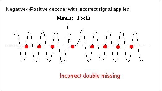
with noise or false signals. The ECU interprets an “event” as the when the VR voltage signal crosses 0V going positive and using the definition of the trigger wheel as set by the user, determines engine RPM and crank position. Below is a photo of the mc22 trigger wheel.
mc22 trigger wheel


An event happens any time a tooth approaches the sensor so the ECU should read 9 events followed by a gap. If the ECU is measuring the gap between events, it should see 8 gaps of relatively equal length (the length will vary due to compression effects) followed by a gap four times the length of the previous 8. However, when I ran the diagnostics tool at engine idle, it became clear why the ECU could not interpret the rpm signal. The diagnostics shows that the ECU was seeing only 7 relatively equal gaps, followed by a gap roughly twice as long and finally a gap about 3 times the length of the first 7. It was almost as if the last tooth had shifted one position later! Graph below for illustration.
Problematic TunerStudio Tooth Logger output at engine idle


I spent ages looking into the cause of this. I bought a cheap USB oscilloscope from EBay to look at the raw signal data from the VR sensor but it turned out to be useless as I misread the specifications and it only had an amplitude range of 1V! I also planned to build a VR conditioner circuit which would convert the VR signal to a square wave Hall signal before input to the Microsquirt ECU. This had been used by a few of the MS forumers to allow the Microsquirt to interpret long tooth trigger wheels. Thanks to EWflyer on the Microsquirt forum for pointing me in that direction!

A few weeks ago I discovered the Arduino board and bought one to play around with. I figured it might have some uses for this project, especially data acquisition and recording. I looked into using the Arduino as an oscilloscope but looking into it, it seemed slightly over my head for the time being. So I discovered then that I could use one of the most basic commands to have the Arduino convert an analogue voltage input to one of the Arduino pins to an integer number and send the number back to the laptop via the serial port. I could then use an auxiliary program to read the integer number stream and write the stream to a text file. The text file could then be opened in Excel and the data displayed on a graph. It is a crude and longer process than I would like but it works! The disadvantage was that it would only read the positive values of the VR signal so I could only display half the signal. For the purposes of identifying any potential issues with the signal, this was acceptable. I may be able to capture the full signal using the Arduino if I research it some more and play around with the code but that’s for another day.
Arduino board hooked up to the VR sensor


When cranking the engine, I was able to get the below plot from the Arduino. The signal looks just the way I would expect so no issues there. The acquisition rate isn’t high enough to identify noise but at the same time, the ECU has inbuilt noise filtering so as long as there is no major noise, it shouldn’t be an issue.
Plot generated from Arduino output


Armed with the confidence that there was nothing wrong with the VR signal, I went back to the microsquirt to see what could be done there. As it happened I solved the issue by accident! While cranking the ignition with the engine stop switch in “off” position, I recorded correct signals with the TunerStudio Tooth Logger.
TunerStudio Tooth Logger diagnostics output when cranking


Recording a data log of the engine cranking also showed a steady cranking rpm signal of ~360rpm without any dropouts! The ~5000rpm spike at the start can be ignored as the ECU will usually skip a certain amount of pulses when starting cranking to allow the signal to settle.
Consistent rpm signal logged at ~360rpm


So quite by accident and even though I was sure I had tried it before, I discovered the issue was simply interference with sharing the VR signal between the stock CDI and the Microsquirt. The next step is to wire up the Microsquirt to drive the coils and get the engine running with Microsquirt controlling the ignition timing and remove the stock CDI altogether. That way I will also be able to identify any issues with high rpm running, signal dropouts or misfiring, etc. Watch this space.

Wednesday, 20 June 2012

RPM signal issues


Time for a bit of an update on this. Unfortunately, I am still chasing a clean, reliable rpm input to the ECU. I have given up on trying to take the input from the coil packs, simply because I would like to have the Microsquirt control ignition timing as well as fuel at some point so there is no point going through the pain twice.

I have made some bit of progress though. First is the trigger wheel definition. I made the fundamental mistake of not physically looking at the wheel myself and relying on pictures from the manual. Of course I didn’t realise that I was looking at pictures of a trigger wheel on an mc17 CBR250 which has the 8-1 trigger wheel. It was only after one of the members on the cbr250.com forum questioned me on this that I realised that the mc22 trigger wheel was a 12-3 definition. That explained some of the erratic signals and why the rpm was jumping to over 21,000rpm at idle. The ECU was expecting teeth where there was none and gaps where there were teeth.

The problem is that this didn’t fix the issue… It did make it better as in the signal peaks read by the ECU were consistent with the actual running rpm of the engine but the signal was still constantly dropping to zero. I tried a few combinations of noise filters within the Microsquirt software but to no avail. After contacting DIYAutotune who I bought the Microsquirt from, they have advised that I try switching to MSII/Extra firmware as it includes some extra diagnostics tools to help isolate the issue. One of these is the trigger tooth logger. I should be able to use this function to see if the ECU is actually reading each trigger tooth correctly and thereby tell me whether I need to concentrate on the VR signal coming into the ECU, or the settings within the ECU.

I have an idea that if the signal entering the ECU is the issue then I will attempt to convert the VR signal to a Hall signal externally using an LM1815 chip and feed that into the ECU. The ECU should be able to read the square wave Hall signal much more easily and cleanly than the AC VR signal.

Also, I have decided to go ahead and modify the GSR400 throttle bodies right away rather than attempt to tune the system on modified carburettors and then do it all again with throttle bodies. I am currently preparing the drawings for the throttle bodies, butterfly valve rods, fuel rail and fuel rail mount adapters so that I can get quotes from a few machine shops and get it kicked off. Once the throttle bodies are ready, that will be a major part of the project complete.

Tuesday, 8 May 2012

Sensor callibration

You've got to love long weekends! I made a bit of progress on the bike the last few days although not quite as much as I would have hoped.

First off was getting my spark back... a little embarassing but it turned out to be stupidly simple! For some reason I still havent figured out, I had decided it was a good idea to disconnect the coils from the loom when I started stripping the bike. And since the connector for the coils is in behind the frame, I didn't actually cop it until after I had tested the VR sensor, CDI, fuses and various other things!

One step in the right direction was to calibrate my MAP sensor. The ECU had been using the calibration data for a common GM sensor to convert the output voltage of my Denso sensor to pressure readings and it had been a bit off. (reading ~190kPa at atmospheric pressure).

I was able to borrow a vacuum gauge from a friend of a friend and connect it via a T-connector into the vacuum tube so the MAP sensor was on one branch of the connector and the gauge was on the other. What I did then was to run the engine, pinch the vacuum tube with a pliers before the T-connector to trap the vacuum and read off voltage from the MAP sensor and vacuum in inches-Hg from the gauge. I was able to get several readings for different pressures by revving the engine to different speeds and closing the throttle to take advantage of the collapsed vacuum formed after the butterfly valves. This allowed me to get as many varied results as possible.


I input the data into a spreadsheet and converted the inches-Hg readings to kPa absolute. I then graphed the data and drew a straight line of best fit and extended the range to go from 0V to 5V as these are the values needed to calibrate the sensor in TunerStudio.


I thought reading the values of pressure read directly from the graph were too inaccurate so I ended up calculating the slope of the line and coming up with an equation for the line and calculating the values of pressure at V=0V and V=5V. I inputted the values into TunerStudio and burned them to the ECU and, voila! Correct pressure readings.


Just to show the pressures being experienced in the manifold at engine idle speed here is another screenshot:


I also hooked up the intake air temperature (IAT) sensor and verified that was working ok.

I was hoping to get the RPM input sorted over the weekend aswel as this would pave the way to get some real work started on installing the rest of the fuel injection hardware. However it proved a little too elusive for me. I tried two different ways of getting a signal to the ECU. The first was to share the VR signal input from the pulse generator with the stock CDI.

The mc22's ignition unit takes its rpm and crank position inputs from an 8-1 trigger wheel mounted on the end of the crank. The wheel induces an alternating voltage across a variable reluctor (VR) sensor as the teeth pass by the sensor. As the wheel has one tooth missing it produces an AC voltage with 7 peaks (7 teeth) and a gap of once per revolution as the space where the missing tooth is passes the sensor. The ignition unit uses the resultant voltage signal to read engine rpm and determine engine position. Since a picture speaks a thousand words, this is pretty much what the output from the VR sensor should look like:


In theory, I should be able to simply define the trigger wheel being used and the ECU should be able to read the engine RPM straight away. Unfortunately this wasnt the case... I was able to get some signal from from the sensor but it looks like the signal was too noisy to be used properly with the microsquirt. It was erratic and would jump from reading 0rpm, to over 21,000rpm even as the engine was only idling. I logged the data over a period of a few seconds in order to get a better picture of what was happening and it is pretty clear how often the signal jumps. The graph you need to be looking at is the top bar and the RPM signal is the yellow line.


I also tried to get an RPM signal from the coil inputs but no success at all. Given that I would eventually like to get the microsquirt controlling ignition as well as fuel I would like to get the VR sensor input working properly. I suspect this will involve some circuitry placed between the sensor and the ECU in order to clean up the signal enough for the microsquirt to be able to use it. This will need some more research though. The sooner I can get a clean and reliable RPM signal to the ECU, the sooner I can get the injectors installed and hooked up.